Cal POLY POMONA BANSHEE UAV
BANSHEE UAV Robotics Ground Station
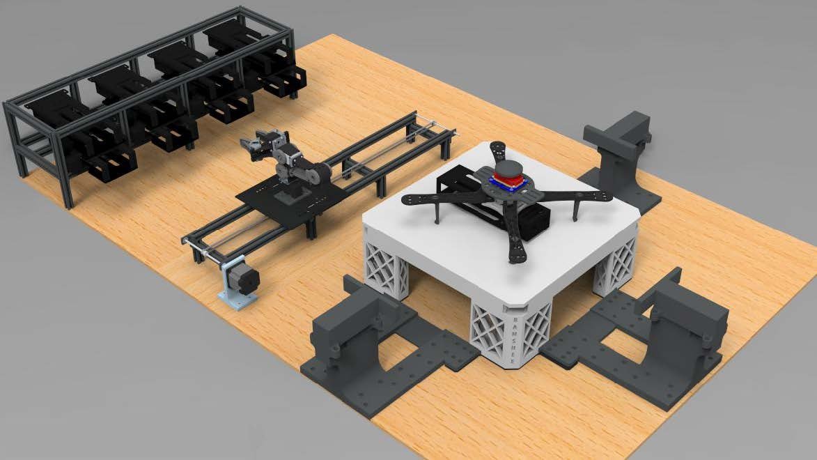
CAD model of the autonomous Robotics Ground Station (RGS) developed for drone battery swapping, featuring a robotic arm, Battery Vending Machine, and Ground Control Station.
Introduction
The BANSHEE UAV (Battery As iNtegrated Structure High Endurance Experimental Unmanned Aerial Vehicle) project focused on developing an autonomous battery swapping system to minimize UAV ground time and extend mission duration. UAVs today are limited by battery life, which reduces flight time and requires manual battery changes. Our system was designed to let a UAV land, automatically swap a depleted LiPo battery, and take off again with minimal downtime and no human involvement. Another focus was to make the system replicable and scalable so it could support larger fleets or be deployed in multiple locations. BANSHEE UAV consists of teams made up of both electrical and computer engineering (ECE) and aerospace engineering (ARO) students.
I was part of the robotics team (ECE) and spent most of the semester working on the power and charging systems for the BVM. My role was to get the battery charging circuit and voltage monitoring and locking solenoid circuit integrated and working reliably. These subsystems were critical for system safety and for laying the groundwork toward eventual fully autonomous battery swaps.
RESULTS and DISCUssion
Phase 1
The first phase of my work was to research and plan the electrical system conversion. The RGS (Robotic Ground Station) had previously used plug-in power for most subsystems, but we were moving to a single 48V 100A main battery for portability and field deployment.
The full system layout is shown in Figures 1 & 2 below:
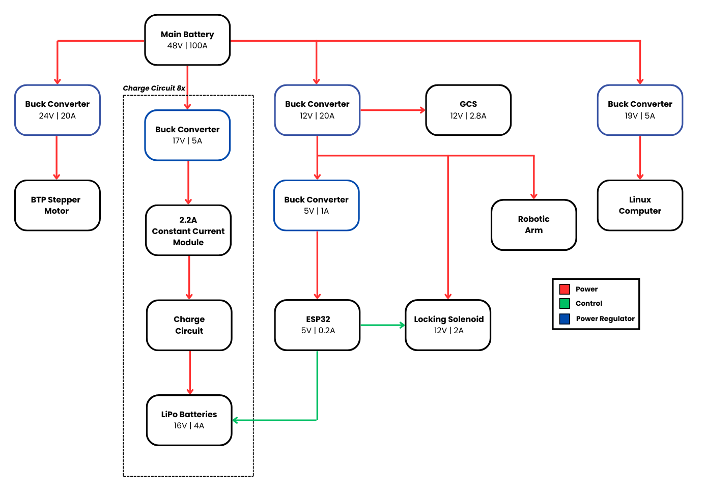
Figure 1 – Full Robotic Ground Station (RGS) power diagram showing battery source and all voltage regulator branches to subsystems
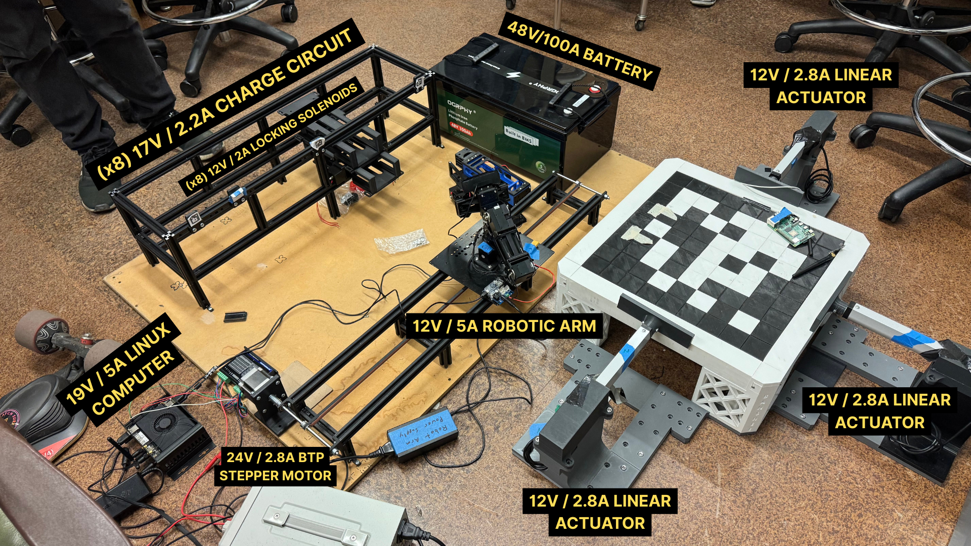
Figure 2 – Full Robotic Ground Station (RGS) power layout showing the 48V battery source and all regulated voltage branches supplying power to subsystem components, including solenoids, actuators, motors, and control units.
The system uses four regulated voltage rails to supply power to key subsystems, with each rail dedicated to a specific function as outlined below:
24V powers the NEMA 23 stepper motor for the BTP rail movement
12V powers the Dynamixel robotic arm, GCS electronics, solenoids, and actuators
5V supplies the ESP32 communication network
19V powers the LattePanda computer that manages system coordination and scheduling
To support this architecture, I researched the use of buck converters to step down the 48V supply to regulated voltages. I confirmed through datasheet reviews and technical documentation that multiple independent buck converters could safely operate from a shared 48V source if they had isolated feedback loops (Texas Instruments, 2020).
Based on this research, we decided to use multiple independent buck converters with isolated feedback loops to power separate branches of the system. This allowed us to confidently design a distributed power architecture with stable, isolated voltage rails.
As part of verifying this approach, I created a dynamic system power budget spreadsheet (Table 1) to track voltage and current values across all branches.
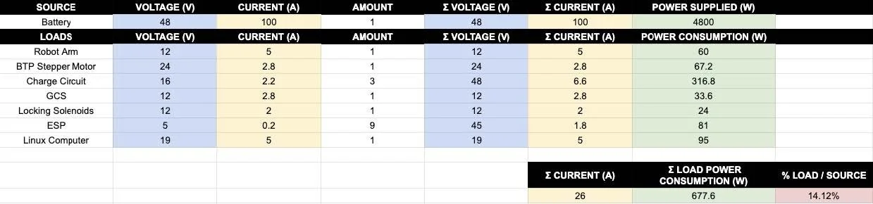
Table 1 – System power tracking spreadsheet showing live voltage, current, and calculated totals for system load validation
The table is color-coded for clarity: blue cells represent voltage, yellow for current, green for calculated power, and red for the % load relative to the main power source. The table automatically updates totals if any design values change, which allowed us to catch potential overcurrent, undervoltage, or unsafe load conditions before hardware damage occurs.
The following equations were used to populate and validate Table 1:

Note that the spreadsheet tracks total current ∑ Current but not total voltage. This is because voltage is not additive across parallel electrical branches — each load receives power from a voltage-regulated rail (e.g., 12V, 24V), and the voltage at each branch remains fixed. In contrast, current does add up across branches, since each load draws a share of current from the same main source (the 48V battery). Tracking the total current ensures we stay within the current handling limits of the battery and regulators, while voltage tracking ensures that each branch remains within its safe operating range.
Phase 2
In the second phase of the semester, I was responsible for building all the wire harnesses, connectors, and interface cables needed for full battery chamber integration. I fabricated 16 hand-crimped standard 5-pin Dupont connector cables to connect the BMS boards to the monitoring PCB and to route the LiPo battery output to the copper contact points inside each battery chamber. Each chamber required two connectors. A close-up of one of these is shown in Figure 3 below:
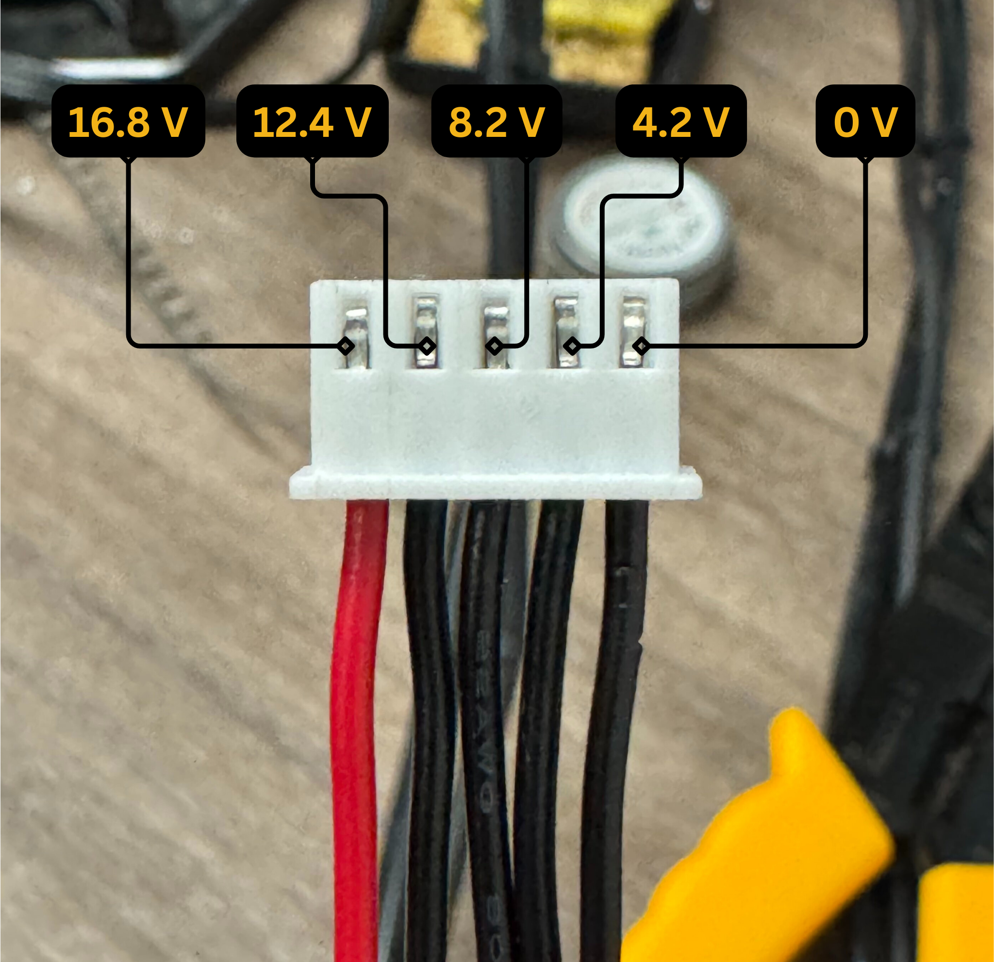
Figure 3 – Hand-crimped 5-pin Dupont connector with labeled voltages for each cell in the 4S LiPo pack: 0 V, 4.2 V, 8.2 V, 12.4 V, and 16.8 V. These voltages are tapped by the BMS for cell-level monitoring and protection.
The corresponding solder points on the BMS board are shown in Figure 4 below:
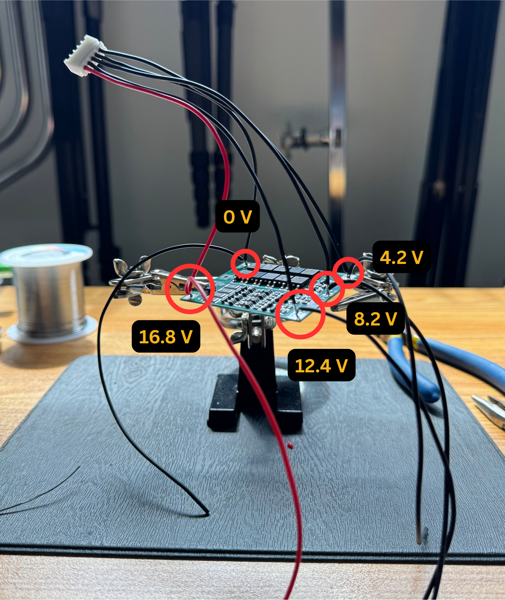
Figure 4 – 5-pin Dupont connector soldered to a 4S BMS board, with each wire tapped to the correct cell voltage for monitoring: 0 V, 4.2 V, 8.2 V, 12.4 V, and 16.8 V. This connection allows the BMS to perform per-cell voltage protection and balancing.
Each battery chamber required two connectors; a total of 16 were fabricated. I also assisted in organizing the system-wide wiring using clean, labeled harnesses to minimize clutter and simplify future troubleshooting.
Phase 3
The final phase was the integration and validation of the power and charging subsystems.
The battery chambers themselves were custom-designed and 3D printed using PLA filament, which let us rapidly prototype and test mechanical alignment and electrical fit inside the BVM. The most complex part of integration was installing the battery charging and control subsystems, shown in Figure 5 below:
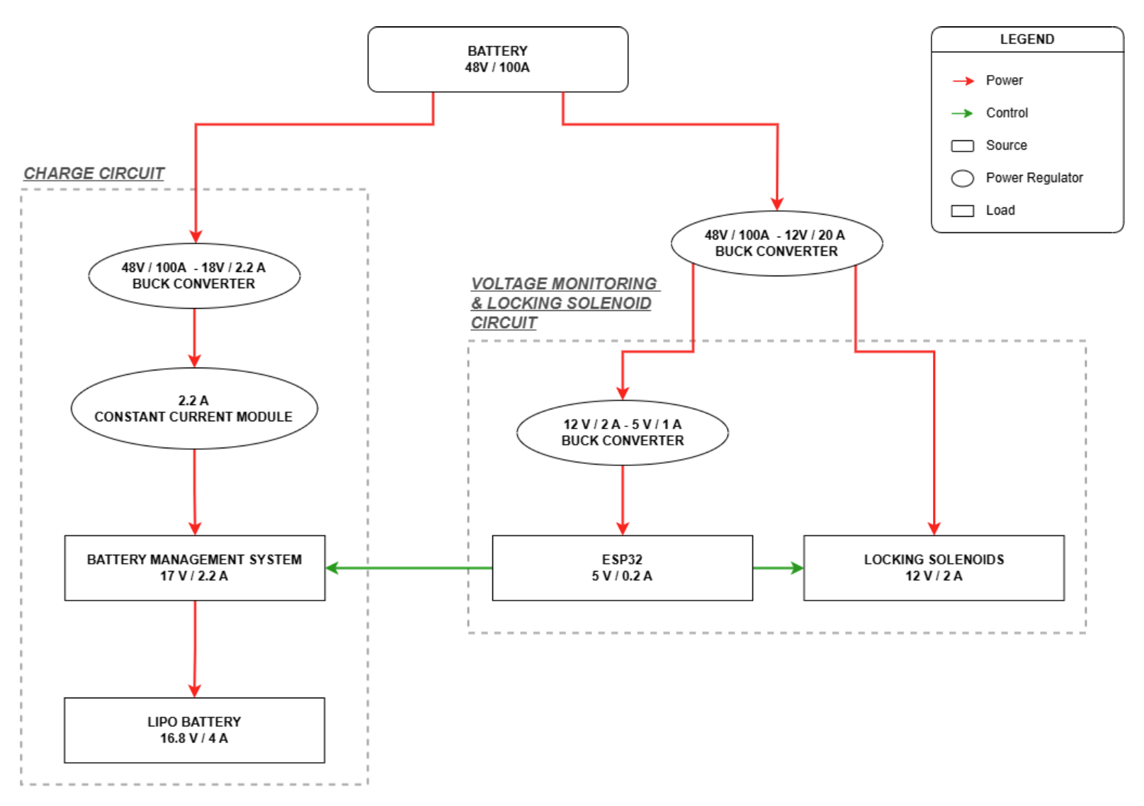
Figure 5 – BANSHEE charging system diagram showing battery charge circuit and voltage monitoring/solenoid locking subcircuits
The charging subsystem uses a dedicated 18V regulator feeding a 2.2A constant current module to limit charging current into the battery packs. Both the constant current module and purchased 4S Battery Management System (BMS) boards were installed in the battery chamber (BVM). The BMS protects each battery pack during charging and discharging. We followed standard LiPo battery handling guidelines to ensure safe operation (Battery University, 2023).Further reference designs and practices were cross-checked using industry examples for BMS cell-tap configurations and connector topologies (Nuvation Engineering, 2023).
The control subsystem runs an ESP32 microcontroller and 12V locking solenoids. The solenoids lock the battery into place to ensure stable contact with the copper charge pins. The ESP32 continuously monitors voltage and controls the locking/unlocking sequence.
Throughout the integration process, continuity testing was critical. After every circuit installation, I verified continuity across all connections before applying power. I then checked voltage and current from each input to output to avoid shorts, missed connections, or wiring errors.
The constant current module, 4S BMS board, ESP32, and locking solenoid PCB were all mounted in the rear of each battery chamber for compactness and modularity. An example installation is shown in Figure 6 below:
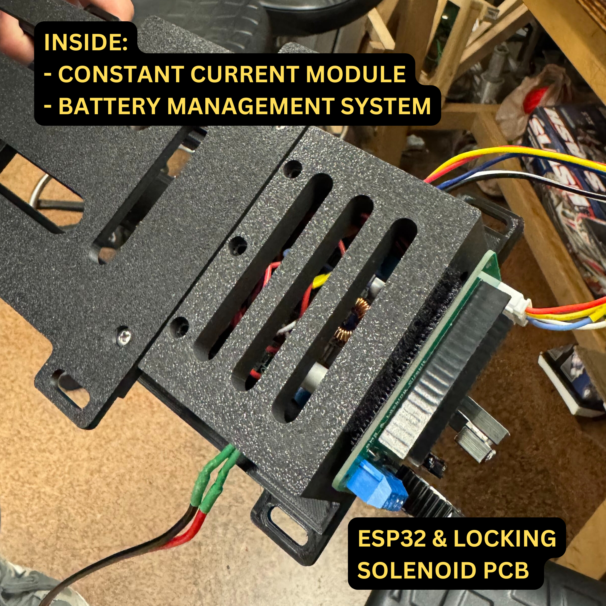
Figure 6 – Photo of charging and monitoring subcircuits — constant current module, BMS, ESP32 & solenoid PCB — integrated into the rear of a 3D printed battery chamber.
By the end of the semester, we successfully achieved full functionality of the battery charging system during controlled bench testing. This laid the groundwork for future steps including scaling up the number of fully operational battery chambers and continuing testing toward full autonomous battery swaps.
VIDEO DEMOS
Robotic Arm Battery Swap Demo (Drone to BVM, No Battery)
This video demonstrates the battery transfer sequence from the drone landing platform on the Ground Control Station (GCS) to the Battery Vending Machine (BVM) using the robotic arm. While the battery is not present in this test, the demo showcases the full motion profile, including arm articulation, rail traversal, and deposit alignment. The sequence highlights the mechanical precision of the system and validates motion timing, clearance, and end-effector positioning as part of the BANSHEE UAV Ground Control System.
BANSHEE UAV RGS Single Charging Circuit Demo
This video showcases a standalone test of one constant-current charging circuit used in the BANSHEE UAV Robotic Ground Station (RGS). The circuit is configured to output 17V at 2.2A, designed to safely charge individual UAV battery packs. Demonstrated without the full battery chamber or housing, this early-stage test validates core functionality including voltage regulation, current control, and status indication under load. The test served as a proof-of-concept for later scaling to a multi-channel array within the Battery Vending Machine (BVM).
WORKS CITED
Texas Instruments. Design Guide for Constant-Current Battery Charging Modules. TI.com, 2023.
Texas Instruments. Understanding Buck Power Stages in Switchmode Power Supplies (SLVA057Q). TI.com, 2020.
Espressif Systems. ESP32 Technical Reference Manual. Espressif.com, 2023.
ROBOTIS Co., Ltd. DYNAMIXEL XM430 / XM540 Series Control Table and User Guide. ROBOTIS e-Manual, 2024.
Battery University. BU-303: Confusion about Ratings. BatteryUniversity.com, 2023.
Nuvation Engineering. Introduction to Battery Management Systems. https://www.nuvation.com